Tuesday, August 23, 2011

MakerBot DC Servo Controller and Quadrature Divider

I've been working on putting together the parts that will run one of the Makery robot arms for an art show. Part of this involves getting a MakerBot DC Servo controller working with the 1000 ppr servos on the arm. At moderate speeds the encoder output is over 25kHz, which is apparently too fast for the servo controller software. If the encoder output changes at all the controller gets confused and runs away.

To address this I loaded a 3 channel quadrature divider program onto an ATmega168. This will divide the quadrature pulse stream by 16 (it is configurable, powers of two up to 16), which should make it slow enough for the servo controller to handle it pretty easily.

I uploaded a video of it running, and added a bazillion annotation bubbles.


The next step is to feed it a pulse stream and see how well it responds.

Sunday, August 7, 2011

Doorbell Upgrade

Recently I discovered that my doorbell has become unreliable. The UPS guy never wants to wait around, and sometimes he takes the packages with him, so I had to do something about this problem. I picked up a new bell at the hardware store for a couple bucks, but it's a cheap plastic model, where the original is a nice heavy metal model with a light in it.

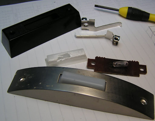
I took apart the old one to see if I could swap parts to reuse the nicer one, and found that the only part that was really a problem was the button, which has degraded on the side facing the afternoon sun.


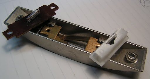
Fortunately the new one is almost exactly the same size, so I swapped it in and had a like-new repair. Cool, 5 minutes and the job was done.


Of course, as soon as I reconnected the wires the little light bulb burned out. It's been running continuously for 5 years now, so I guess that isn't too bad a lifetime, but I'd like the button to be lit, so I'll need to get that little guy out of there and find a replacement.


I'd probably have to spend $15 on a new lighted switch to get one of those little 20VAC bulbs, so I'll be looking for something else. Twenty volts is a little low for neon bulbs and electroluminescent wire or film, so I guess it'll have to be an LED. Fortunately I've got a ton of those. Red would be neat, but maybe a little boring. I have a bunch of IR LED's and some luminescent powder, so I could coat the inside of the button and make it glow, but I'll probably have to replace it again in a few years, and I don't want to have to reapply the glow powder. So I think I'll go with one of the blue LEDs I had left over from my binary clock project.

The LED will need a diode to block half the AC voltage and a resistor to limit the current. I used 33mA for the clock, and that's plenty bright for this, so I found an ~800 ohm resistor for this.


There isn't much space in the doorbell, so I marked where the circuit board did not lay on top of the metal contacts, connected the resistor and diode and laid them out to see where I'd need new holes for the leads.


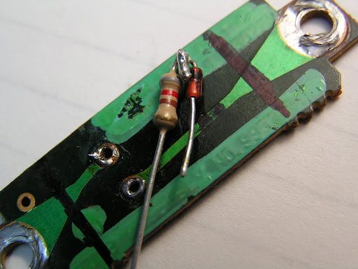
Looks like it will fit without much trouble. There is just enough room between the PCB and the wall to avoid squashing the resistor. I marked the trace where the new holes will go and drilled them out.


Then cut the trace between the new holes.


A little work with a needle file to make some new pads around the holes...


And I can solder in the new components.


Next the LED goes in, but first I lopped off the lens with the dremel to turn the end of the LED into a diffuser. There isn't enough room in the switch body to stand it up, and the beam is too narrow for that anyway.


Before I reassembled the switch I took the chance to bend the contacts into a higher arc so that the button only has to be pushed about 2mm to make contact. It was set for more like 3mm, which put the button almost inside the switch body, which was contributing to the difficulty of getting it to work.

I put it back together and hooked it up, and it's working as planned:


A neat improvement on this would be to replace the factory board with a custom board with an ATtiny13 and a couple SMT RGB LEDs so that the button could cycle through a set of colors. It would reset when the switch is pressed, so the startup code could do a neat flash of colors to indicate that it had been pressed before returning to the usual slow color cycle.

Saturday, August 6, 2011

Motorized Potentiometer

I had a broken micro RC car that used a gearbox with a tiny potentiometer on it for controlling the steering angle. I thought it would be interesting to replace the little potentiometer with a regular sized version so I could set the position either manually or from a microcontroller by driving the motor.

I drilled a bit of brass rod to fit over the gearbox output and to fit the stub of shaft on the back of the pot. I used some loctite and epoxy to connect the shafts together, and ran it a bit to get it all concentric, then epoxied a bit of aluminum strap to both.


The next step is to come up with some code to read the pot and drive the motor to the commanded position. Since it holds position without power to the motor, the h-bridge can be left idle except when it is moving to a commanded position, so that a user can turn the knob to adjust a setting.

Monday, August 1, 2011

Stepper Heat Sinks

I've been using some Pololu A4983 Stepper Motor Driver Carrier boards to run the stepper motors on my mill, but I noticed the other day that they are overheating and cutting out briefly, even with a small fan blowing on them. This isn't surprising, since I'm not running them with any sort of heat sink. As a test I held a bit of brass rod against the top of one of the chips and the glitching went away immediately.

To make some heat sinks I decided I would cut down a heat sink I pulled out of some salvage equipment. Probably a computer monitor. I stopped by the Makery to use the sawzall and scroll saw to chop it up into suitably sized bits, then returned home to finish them off.


I spent some time with the dremel to make a 5x5mm pad on the bottom of the heatsink. I just eyeballed it, but the micrometer says they are all within 0.15mm of the target size, except one, which was off by 0.5mm. Not bad for eyeballing.


I didn't have any thermal tape, which would be perfect for this, so I just put some thermal compound on it to be a weak adhesive. I'll just have to be careful with them for now. Once I have the machine running with this cobbled-together electronics setup I'll use it to make something to mount the parts more robustly.


Now they just have to sit around so the heatsink compound can set up a bit.

Binding Books

This weekend some friends and I spent a few hours working on binding some books. We started with the paper from some drawing pads which we folded in half in sets of 4 to 6 to form signatures. We stacked between 5 and 8 of the signatures and stitched book tapes to them, then glued on the mull to form the book block.


I cut some 1/8th inch hardboard to make coverboards and the spine. To this we glued some card stock to make the hinge, and then to the coverboards we glued some fabrics.


The book block was then pasted into the cover along with end papers made from scrapbooking papers. This was then clamped to prevent the pages wrinkling while the paste dried.


The spines ended up being to wide IMO, I think I prefer them to be about 1/8 to a 1/4 inch narrower than we made these. On the other hand, we can put lots of stuff between the pages of these books and then the spine will be just right.

Zinc Casting

Did a quick zinc casting of a small knight figure. This was a sand casting demo for some friends who are interested in the skill. I was surprised that the shaft of the mace came out, since it is only about 2mm in diameter.

The casting ended up with a poor surface finish. I haven't worked out the main cause of this. It may be related to pouring temperature or venting.

For small things like this I think it would be interesting to try building a small electric furnace.